Hello again,
preamble: I have to issue the command
in order for the device /dev/spidev0.0 and /dev/spidev0.1 to appear.
Physicalinterface.conf reads:
[MAX]
deviceType = cc1100
device = /dev/spidev0.0
responseDelay = 45
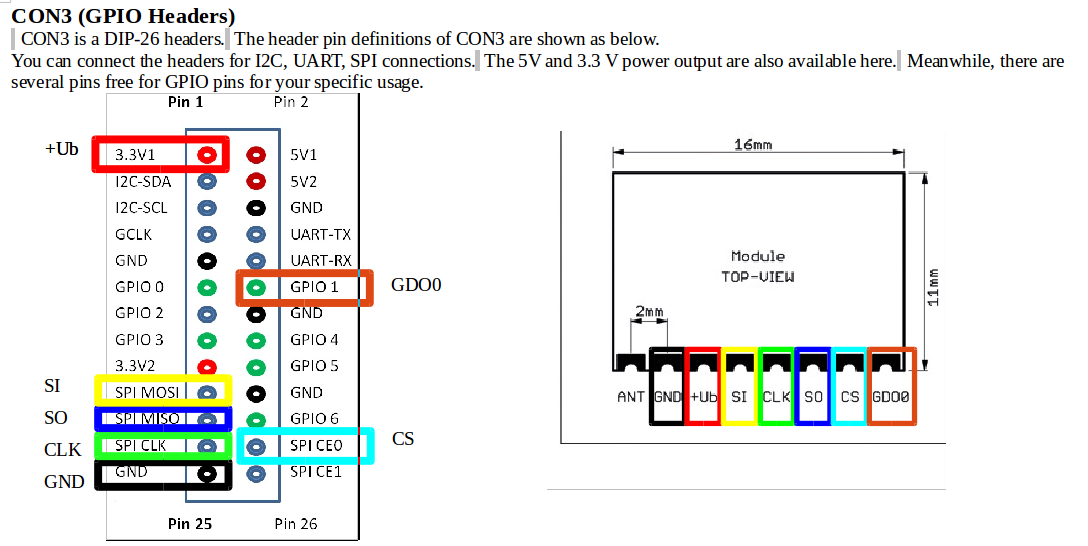
# "0" if GDO0 is connected to GPIO of Rasberry Pi or "2" if GDO2 is connected
# You only need one GDO (0 or 2), it doesn't matter which one you use.
interruptPin = 0
# GPIO pin on Raspberry Pi the GDO of the module is connected to.
gpio1 = 1
At this point if I start homegear I get the following output:
# /etc/
init.d/homegear start
12/28/14 16:12:12.404 Info: Loading family module mod_philipshue.so
12/28/14 16:12:12.415 Info: Loading family module mod_max.so
12/28/14 16:12:12.428 Info: Loading family module mod_homematicbidcos.so
12/28/14 16:12:12.446 Info: Loading family module mod_insteon.so
12/28/14 16:12:12.458 Info: Loading family module mod_homematicwired.so
12/28/14 16:12:12.475 Error in file Modules/Base/Systems/IPhysicalInterface.cpp line 649 in function virtual void BaseLib::Systems::IPhysicalInterface::setGPIOEdge(uint32_t, BaseLib::Systems::IPhysicalInterface::GPIOEdge::Enum): Could not write to edge file (/sys/class/gpio/gpio1/edge) of GPIO with index 1: No such file or directory
12/28/14 16:12:12.475 Error in file Modules/Base/Systems/IPhysicalInterface.cpp line 649 in function virtual void BaseLib::Systems::IPhysicalInterface::setGPIOEdge(uint32_t, BaseLib::Systems::IPhysicalInterface::GPIOEdge::Enum): Could not write to edge file (/sys/class/gpio/gpio1/edge) of GPIO with index 1: No such file or directory
12/28/14 16:12:12.476 Info: Disposing family module mod_philipshue.so
12/28/14 16:12:12.476 Info: Disposing family module mod_max.so
12/28/14 16:12:12.477 Info: Disposing family module mod_insteon.so
12/28/14 16:12:12.477 Info: Disposing family module mod_homematicwired.so
12/28/14 16:12:12.478 Info: Disposing family module mod_homematicbidcos.so
[....] Starting Homegear: homegear12/28/14 16:12:12.524 Loading RPC server settings from /etc/homegear/rpcservers.conf
12/28/14 16:12:12.526 Loading RPC client settings from /etc/homegear/rpcclients.conf
. ok
And if fact the edge file is not there:
# ls -lah /sys/class/gpio/gpio1/
total 0
drwxr-xr-x 3 root     root        0 Jan  1 01:02 .
drwxr-xr-x 4 root     root        0 Jan  1 01:00 ..
-rw-r--r-- 1 root     root     4.0K Jan  1 01:05 active_low
lrwxrwxrwx 1 root     root        0 Jan  1 01:05 device -> ../../../gpio-sunxi
-rw-r--r-- 1 root     root     4.0K Jan  1 01:02 direction
drwxr-xr-x 2 root     root        0 Jan  1 01:05 power
-rw-r--r-- 1 root     root     4.0K Jan  1 01:05 pull
lrwxrwxrwx 1 root     root        0 Jan  1 01:02 subsystem -> ../../../../../class/gpio
-rw-r--r-- 1 root     root     4.0K Jan  1 01:02 uevent
-r--r----- 1 homegear homegear 4.0K Jan  1 01:02 value
I don’t see any traffic in the log, even at debuglevel 10. But homegear.err is empty and in the homegear.log file I see:
12/28/14 16:12:12.681 Module MAX: Loading XML RPC devices...
12/28/14 16:12:12.789 Info: Not initializing device family Philips hue, because no physical interface was found.
12/28/14 16:12:12.790 Loading devices...
12/28/14 16:12:12.791 Module MAX: Loading device 3
12/28/14 16:12:12.793 Module MAX: Loading device 4
12/28/14 16:12:12.795 Start listening for packets...
If I connect (homegear -r) and look around I see this:
> families list
   ID │ Name
──────┼───────────────────────────────
    4 │ MAX!
──────┴───────────────────────────────
> families select 4
Device family "MAX!" selected.
For information about the family's commands type: "help"
(Family)> devices list
      ID │ Address │ Serial Number │     Type
─────────┼─────────┼───────────────┼─────────
       3 │  FD3D45 │    VMC4265713 │ FFFFFFFD
       4 │  FEB8BA │    VMS6191689 │ FFFFFFFE
─────────┴─────────┴───────────────┴─────────
(Family)> devices select 3
Device selected.
For information about the device's commands type: "help"
(Device)> help
List of commands (shortcut in brackets):

For more information about the indivual command type: COMMAND help

pairing on (pon)	Enables pairing mode
pairing off (pof)	Disables pairing mode
peers list (ls)		List all peers
peers remove (prm)	Remove a peer (without unpairing)
peers select (ps)	Select a peer
peers setname (pn)	Name a peer
peers unpair (pup)	Unpair a peer
unselect (u)		Unselect this device
(Device)> devices select 4
Device selected.
For information about the device's commands type: "help"
(Device)> help
List of commands:

For more information about the indivual command type: COMMAND help

enable			Enables the device if it was disabled
disable			Disables the device
filters list		Lists all packet filters
filters add		Adds a packet filter
filters remove		Removes a packet filter
send			Sends a MAX packet
(Device)>
But, as sayed before: I can’t see anything in the log even at debuglevel10.
At this point if I issue the command
#homegear -s root root
I start seeing packets in the log!
At debug level 4 I see nothing until I initialize pairing from the valve, at this point I see:
12/28/14 16:19:50.564 Module MAX: Warning: Tried to import MAX packet larger than 200 bytes.
12/28/14 16:19:50.563 MAX packet received (cc1100): 09000000000000000000
12/28/14 16:19:55.563 MAX packet received (cc1100, RSSI: 0x3A): 85C5F44158212DEDF9F126EB1E8F7203108F995977E58D33F56F617F1C571AB6C80093728862E12403B7094C0C9C4A8824BC4F9A6F123B045DC333D9A3D7B2C85BC5F44158212DEDF9F126EB1E8F7203108F995977E58D33F56F617F1C571AB6C80093728862E12403B7094C0C9C4A8824BC4F9A6F123B045DC333D9A3D7B2C8C85BC5F44158
12/28/14 16:19:55.563 MAX packet received (cc1100, RSSI: 0x67): 2DC5C5C5C5C5C5C5C5C5C5C5C5C5C5C5C5C5C5C5C5C5C5C5C5C5C5C5C5C5C5C5C5C5C5C5C5C5C5C5C5C5C5C5C5C5
12/28/14 16:20:00.563 MAX packet received (cc1100, RSSI: 0x34): 86C5F44158212DEDF9F126EB1E8F7203108F995977E58D33F56F617F1C571AB6C80093728862E12403B7094C0C9C4A8824BC4F9A6F123B045DC333D9A3D7B2C85BC5F44158212DEDF9F126EB1E8F7203108F995977E58D33F56F617F1C571AB6C80093728862E12403B7094C0C9C4A8824BC4F9A6F123B045DC333D9A3D7B2C8C85BC5F4415821
12/28/14 16:20:00.564 Module MAX: Warning: Tried to import MAX packet larger than 200 bytes.
12/28/14 16:20:00.564 MAX packet received (cc1100): 09000000000000000000
12/28/14 16:20:05.563 MAX packet received (cc1100, RSSI: 0x34): 86C5F44158212DEDF9F126EB1E8F7203108F995977E58D33F56F617F1C571AB6C80093728862E12403B7094C0C9C4A8824BC4F9A6F123B045DC333D9A3D7B2C85BC5F44158212DEDF9F126EB1E8F7203108F995977E58D33F56F617F1C571AB6C80093728862E12403B7094C0C9C4A8824BC4F9A6F123B045DC333D9A3D7B2C8C85BC5F4415821
12/28/14 16:20:05.564 Module MAX: Warning: Tried to import MAX packet larger than 200 bytes.
12/28/14 16:20:05.564 MAX packet received (cc1100): 09000000000000000000
12/28/14 16:20:10.564 MAX packet received (cc1100, RSSI: 0x4D): 88C5F44158212DEDF9F126EB1E8F7203108F995977E58D33F56F617F1C571AB6C80093728862E12403B7094C0C9C4A8824BC4F9A6F123B045DC333D9A3D7B2C85BC5F44158212DEDF9F126EB1E8F7203108F995977E58D33F56F617F1C571AB6C80093728862E12403B7094C0C9C4A8824BC4F9A6F123B045DC333D9A3D7B2C8C85BC5F44158212DED
12/28/14 16:20:10.564 Module MAX: Warning: Tried to import MAX packet larger than 200 bytes.
12/28/14 16:20:10.564 MAX packet received (cc1100): 09000000000000000000
12/28/14 16:20:15.564 MAX packet received (cc1100, RSSI: 0x3A): 85C5F44158212DEDF9F126EB1E8F7203108F995977E58D33F56F617F1C571AB6C80093728862E12403B7094C0C9C4A8824BC4F9A6F123B045DC333D9A3D7B2C85BC5F44158212DEDF9F126EB1E8F7203108F995977E58D33F56F617F1C571AB6C80093728862E12403B7094C0C9C4A8824BC4F9A6F123B045DC333D9A3D7B2C8C85BC5F44158
12/28/14 16:20:15.564 MAX packet received (cc1100, RSSI: 0x25): 2DC5F44158212DEDF9F126EB1E8F7203108F995977E58D33F56F617F1C571AB6C80093728862E12403B7094C0C9C
12/28/14 16:20:15.565 MAX packet received (cc1100, RSSI: 0x67): 88C5C5C5C5C5C5C5C5C5C5C5C5C5C5C5C5C5C5C5C5C5C5C5C5C5C5C5C5C5C5C5C5C5C5C5C5C5C5C5C5C5C5C5C5C5C5C5C5C5C5C5C5C5C5C5C5C5C5C5C5C5C5C5C5C5C5C5C5C5C5C5C5C5C5C5C5C5C5C5C5C5C5C5C5C5C5C5C5C5C5C5C5C5C5C5C5C5C5C5C5C5C5C5C5C5C5C5C5C5C5C5C5C5C5C5C5C5C5C5C5C5C5C5C5C5C5C5C5C5C5C5C5C5C5C5C5
At debug level 5, even when not pairing, the logfile is flooded (literally) with:
12/28/14 16:22:31.568 Module MAX: TI CC110X "cc1100": Debug: MAX! packet received, but CRC failed.
12/28/14 16:22:31.568 Module MAX: TI CC110X "cc1100": Debug: MAX! packet received, but CRC failed.
12/28/14 16:22:31.568 Module MAX: TI CC110X "cc1100": Debug: MAX! packet received, but CRC failed.
12/28/14 16:22:31.568 Module MAX: TI CC110X "cc1100": Debug: MAX! packet received, but CRC failed.
12/28/14 16:22:31.569 Module MAX: TI CC110X "cc1100": Debug: MAX! packet received, but CRC failed.
12/28/14 16:22:31.569 Module MAX: TI CC110X "cc1100": Debug: MAX! packet received, but CRC failed.
12/28/14 16:22:31.569 Module MAX: TI CC110X "cc1100": Debug: MAX! packet received, but CRC failed.
12/28/14 16:22:31.569 Module MAX: TI CC110X "cc1100": Debug: MAX! packet received, but CRC failed.
12/28/14 16:22:31.570 Module MAX: TI CC110X "cc1100": Debug: MAX! packet received, but CRC failed.
12/28/14 16:22:31.570 Module MAX: TI CC110X "cc1100": Debug: MAX! packet received, but CRC failed.
12/28/14 16:22:31.570 Module MAX: TI CC110X "cc1100": Debug: MAX! packet received, but CRC failed.
12/28/14 16:22:31.571 Module MAX: TI CC110X "cc1100": Debug: MAX! packet received, but CRC failed.
12/28/14 16:22:31.571 Module MAX: TI CC110X "cc1100": Debug: MAX! packet received, but CRC failed.
12/28/14 16:22:31.571 Module MAX: TI CC110X "cc1100": Debug: MAX! packet received, but CRC failed.
12/28/14 16:22:31.572 Module MAX: TI CC110X "cc1100": Debug: MAX! packet received, but CRC failed.
At debuglevel 6
12/28/14 16:23:18.160 Module MAX: TI CC110X "cc1100": Debug: Sending: 3A
12/28/14 16:23:18.160 Module MAX: TI CC110X "cc1100": Debug: Received: 1F
12/28/14 16:23:18.161 Module MAX: TI CC110X "cc1100": Debug: Sending: 34
12/28/14 16:23:18.161 Module MAX: TI CC110X "cc1100": Debug: Received: 1F
12/28/14 16:23:18.161 Module MAX: TI CC110X "cc1100": Debug: Sending: F300
12/28/14 16:23:18.161 Module MAX: TI CC110X "cc1100": Debug: Received: 1000
12/28/14 16:23:18.161 Module MAX: TI CC110X "cc1100": Debug: MAX! packet received, but CRC failed.
12/28/14 16:23:18.161 Module MAX: TI CC110X "cc1100": Debug: Sending: 3A
12/28/14 16:23:18.162 Module MAX: TI CC110X "cc1100": Debug: Received: 1F
12/28/14 16:23:18.162 Module MAX: TI CC110X "cc1100": Debug: Sending: 34
12/28/14 16:23:18.162 Module MAX: TI CC110X "cc1100": Debug: Received: 1F
12/28/14 16:23:18.162 Module MAX: TI CC110X "cc1100": Debug: Sending: F300
12/28/14 16:23:18.162 Module MAX: TI CC110X "cc1100": Debug: Received: 1000
12/28/14 16:23:18.163 Module MAX: TI CC110X "cc1100": Debug: MAX! packet received, but CRC failed.
12/28/14 16:23:18.163 Module MAX: TI CC110X "cc1100": Debug: Sending: 3A
12/28/14 16:23:18.163 Module MAX: TI CC110X "cc1100": Debug: Received: 1F
12/28/14 16:23:18.163 Module MAX: TI CC110X "cc1100": Debug: Sending: 34
12/28/14 16:23:18.163 Module MAX: TI CC110X "cc1100": Debug: Received: 1F
12/28/14 16:23:18.163 Module MAX: TI CC110X "cc1100": Debug: Sending: F300
12/28/14 16:23:18.164 Module MAX: TI CC110X "cc1100": Debug: Received: 1000
12/28/14 16:23:18.164 Module MAX: TI CC110X "cc1100": Debug: MAX! packet received, but CRC failed.
I hope to have provided what’s needed!
Kind regards,
Daniele


 .
.